Examples are valid for:
TMflow Software version: 2.20 or above.
TM Robot Hardware version: All versions.
Other specific requirements:
- Photoelectric sensor (Panasonic EX-11A)
- Air Gripper (SMC MFH2 20D1 + Finger)
- Bin Frame Gripper
Note that older or newer software versions may have different results.
Scenario Introduction #
Environment Arrangement #
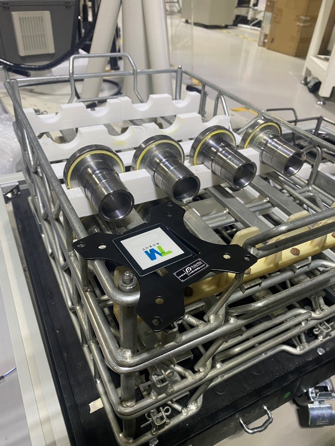
There are two stacks of material trays in the loading area. Workpieces are placed in material trays stacked on racks. One stack contains raw material, and the other stack contains finished material. This case uses a speed reducer shaft as the workpiece.
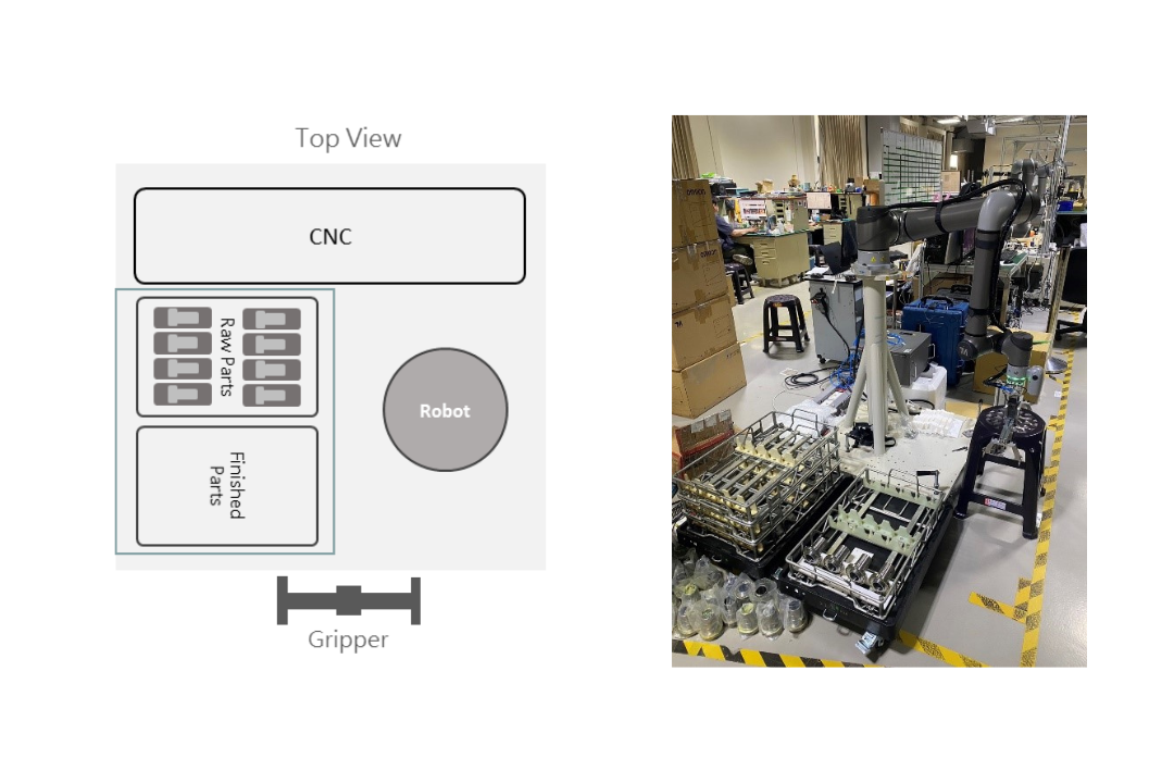
Machine Tending Process #
The loading/unloading process is divided into two parts :
- CNC Loading and Unloading
After the robot positions itself in front of the raw/finished material bins, it begins by loading workpieces from the raw bin area into the CNC machine. Once processing is complete, the robot unloads the workpiece from the CNC and places it in the finished bin. This process repeats until the raw bin is empty.
- Bin Stacking
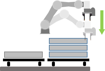
The empty raw material bin is picked up and stacked up onto the finished bin area to prepare for the next cycle. The process is illustrated as follows.
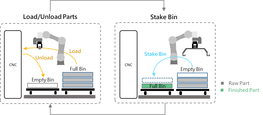
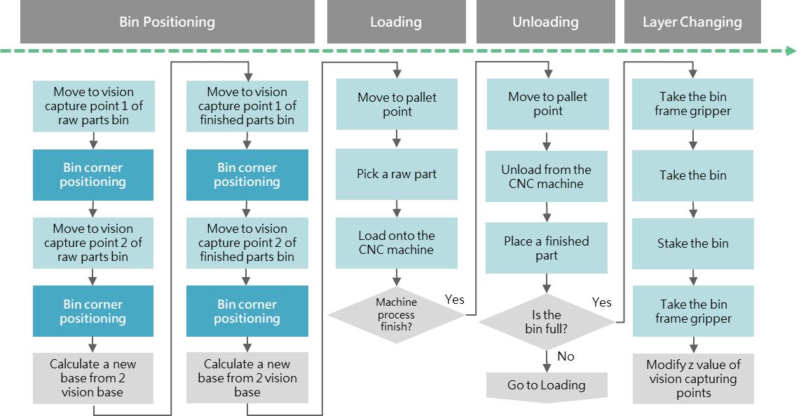
The TMflow process contains four main steps:
- Bin positioning
- Loading to CNC
- Unloading from CNC
- Switching to the next bin layer
Before picking up the bin, the bin hook must be gripped
Technical Explanation and Function Settings #
Vision Positioning #
- Diagonal bin positioning pins are used as visual features. Due to manufacturing variances and wear on the bin appearance, traditional template matching is inadequate. Hence, AI-based object detection is used. The model trained with augmented data under various lighting conditions, which improves recognition robustness and accuracy despite shape differences in positioning pins.
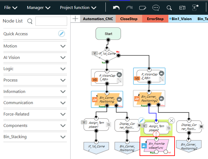
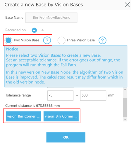
- To determine bin orientation, two diagonal corners are captured to obtain two Vision Bases. A NewBase node is used to synthesize the bin coordinate frame from these two Vision Bases. All subsequent robot teaching is based on this synthesized coordinate.
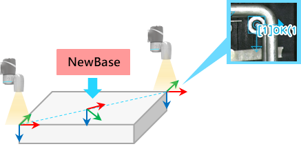
In the TMflow :
- Create two Vision Jobs to detect the two corners of the bin.
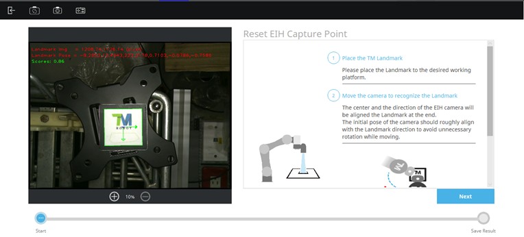
- Define Vision Capture Points : Position the camera using a board placed on the top bin surface. Align the Landmark on the board edge with the bin. Move the arm to position the camera above the Landmark.
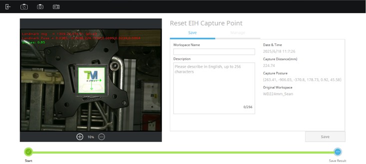
In the vision job editor, use the “Reset Capture Point” feature (available in TMflow 2.20) under the “Set Workspace” setting. Choose the same workspace used during object detection image data collection.
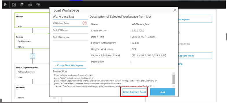
Press “Next” button and the robot will be moving until recovering the original working height, and record the current pose or save it as a new workspace.
After both vision tasks have been executed, create a NewBase node and select the two Vision Jobs used—this completes the setup for the synthesized coordinate system of the bin.
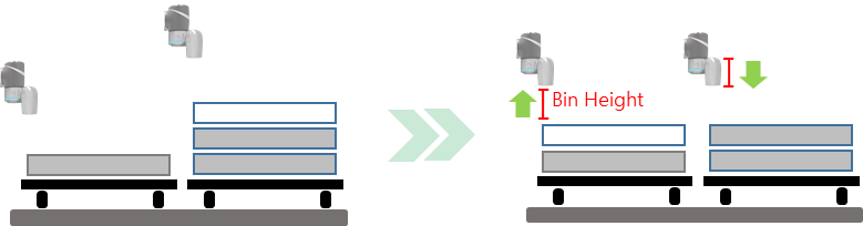
- The camera capture position changes in height according to the placement or removal of material bins. When a raw material bin is stacked onto the finished material stack, the capture position for the next raw bin cycle decreases by the height of one bin, while the finished bin capture position increases by the height of one bin, as illustrated below.
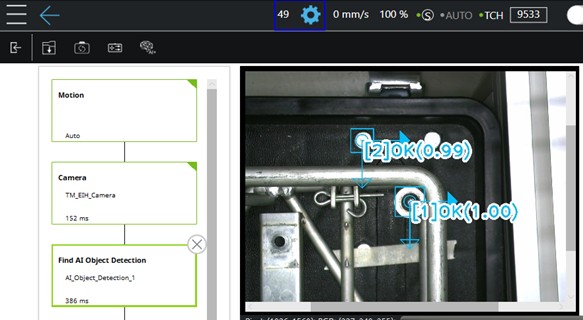
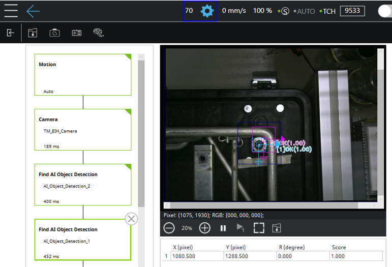
- Due to the visual similarity between the screw of the background cart and the positioning pin, combined with the influence of ambient lighting, positioning erros may occasionally occur, as shown in the image below :
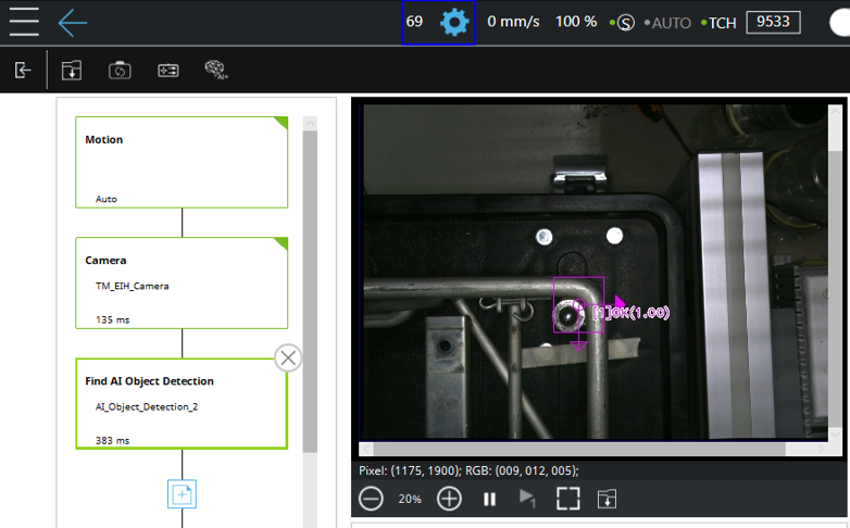
In such cases, two object detection models can be used. The first model identifies a broader, unique feature for coarse positioning, as shown in the figure below. At this stage, the bounding box can encompass the positioning pin along with the surrounding bin frame, creating a distinctive feature that is less prone to misidentification.
The second Object Detection model performs fine positioning by detecting the positioning pin with a bounding box tightly aligned to its edges. In the Find module, a search range is defined, which dynamically shifts based on the result of the previous Find step. Only objects detected within this search range will be output, effectively eliminating background interference.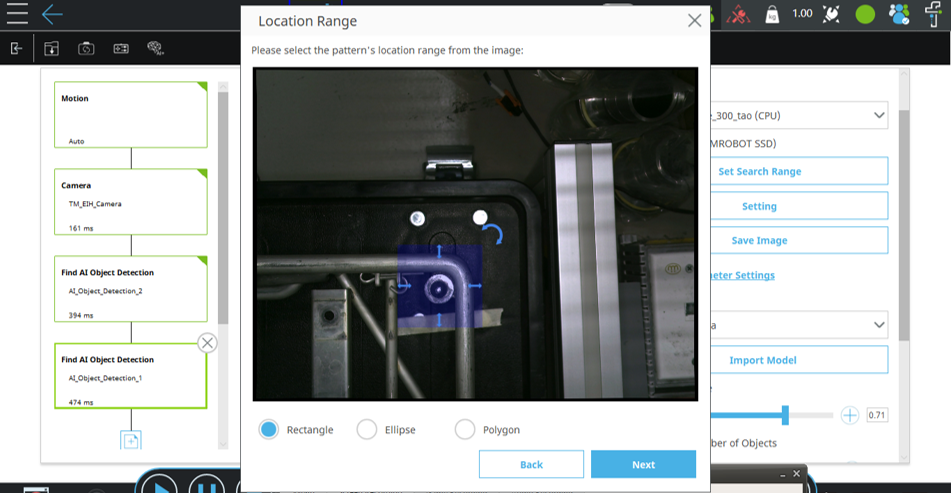
Depth Detection #
The photoelectric sensor on the fingertip has two functions:
Detect Bin Stack Height #
At the beginning of the cycle, the robot probes down from a known height until the sensor beam is interrupted. The current end-effector Z-coordinate is used to estimate the height of the bin stack. Since a single bin’s height is known, the number of stacked bins can be deduced. Loading/unloading operations can then be performed at the appropriate height.
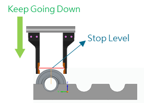
Grasp Depth Compensation: #
Manual teaching of pallet heights can be slightly inaccurate, and minor variations between bins may cause picking failures due to incorrect depth. As shown in the illustration, this can lead to inconsistent pick positions.
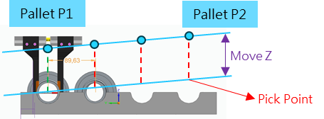
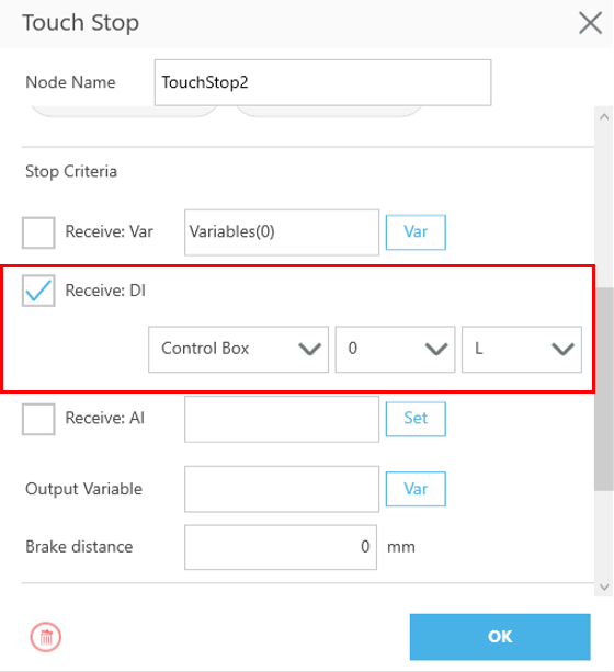
To solve this, a photoelectric light gate is mounted on the fingers. When blocked (Input signal = Low), paired with the Touch Stop function, the gripper descends along the Z-axis until the light gate is triggered. It then descends a predefined distance to grip the workpiece. This ensures consistent pick depth and compensates for height variation.
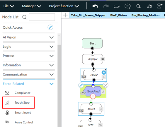
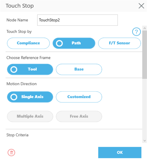
The Touch Stop node is configured as shown in the figure below. Connect a Touch Stop node after the Pallet node. In the node settings, select Path as the movement type, choose Tool as the reference coordinate system, set the movement direction to Single Axis (Z-axis), and define the stop condition as the input pin connected to the photoelectric sensor at the end effector. The descent will stop when the input signal becomes Low.