Examples are valid for:
TMflow Software version: 2.14 or above.
TM Robot Hardware version: HW5 or above
Note that older or newer software versions may have different results.
Safety Function List #
| SF# | Name | Robot Stopping Function | Stop Category | Structure Category | PL | ||||||||||||||||||||||||||||||||||
| SF0 | Robot Stick ESTOP | Emergency Stop | Category 1 Stop | Cat. 3
Structure |
d | ||||||||||||||||||||||||||||||||||
| SF1 | User Connected ESTOP Input | Emergency Stop | Category 1 Stop | ||||||||||||||||||||||||||||||||||||
| SF2 | Encoder Standstill Output | (Output function) | |||||||||||||||||||||||||||||||||||||
| SF3 | User Connected External Safeguard Input | Protective Stop | Category 2 Stop | ||||||||||||||||||||||||||||||||||||
| SF4 | Additional Joint Torque Monitoring | Protective Stop | Category 2 Stop | ||||||||||||||||||||||||||||||||||||
| SF5 | Joint Position Limit | Protective Stop | Category 2 Stop | ||||||||||||||||||||||||||||||||||||
| SF6 | Joint Speed Limit | Protective Stop | Category 2 Stop | ||||||||||||||||||||||||||||||||||||
| SF7 | Speed Limit | Protective Stop | Category 2 Stop | ||||||||||||||||||||||||||||||||||||
| SF8 | Additional Force Limit | Protective Stop | Category 2 Stop | ||||||||||||||||||||||||||||||||||||
| SF9 | User Connected External Safeguard Input for Human–Machine Safety Settings | (Change safety criteria) | |||||||||||||||||||||||||||||||||||||
| SF10 | Robot ESTOP Output | (Output function) | |||||||||||||||||||||||||||||||||||||
| SF11 | User Connected External Safeguard Output | (Output function) | |||||||||||||||||||||||||||||||||||||
| SF12 | Robot Human–Machine Safety Settings Output | (Output function) | |||||||||||||||||||||||||||||||||||||
| SF13 | Robot Recovery Mode Output | (Output function) | |||||||||||||||||||||||||||||||||||||
| SF14 | Robot Moving Output | (Output function) | |||||||||||||||||||||||||||||||||||||
| SF15 | User Connected Enabling Switch Input | Protective Stop | Category 2 Stop | ||||||||||||||||||||||||||||||||||||
| SF16 | User Connected ESTOP Input without Robot ESTOP Output | Emergency Stop | Category 1 Stop | ||||||||||||||||||||||||||||||||||||
| SF17 | Cartesian Limit A | Protective Stop | Category 2 Stop | ||||||||||||||||||||||||||||||||||||
| SF18 | Cartesian Limit B | (Change safety criteria) | |||||||||||||||||||||||||||||||||||||
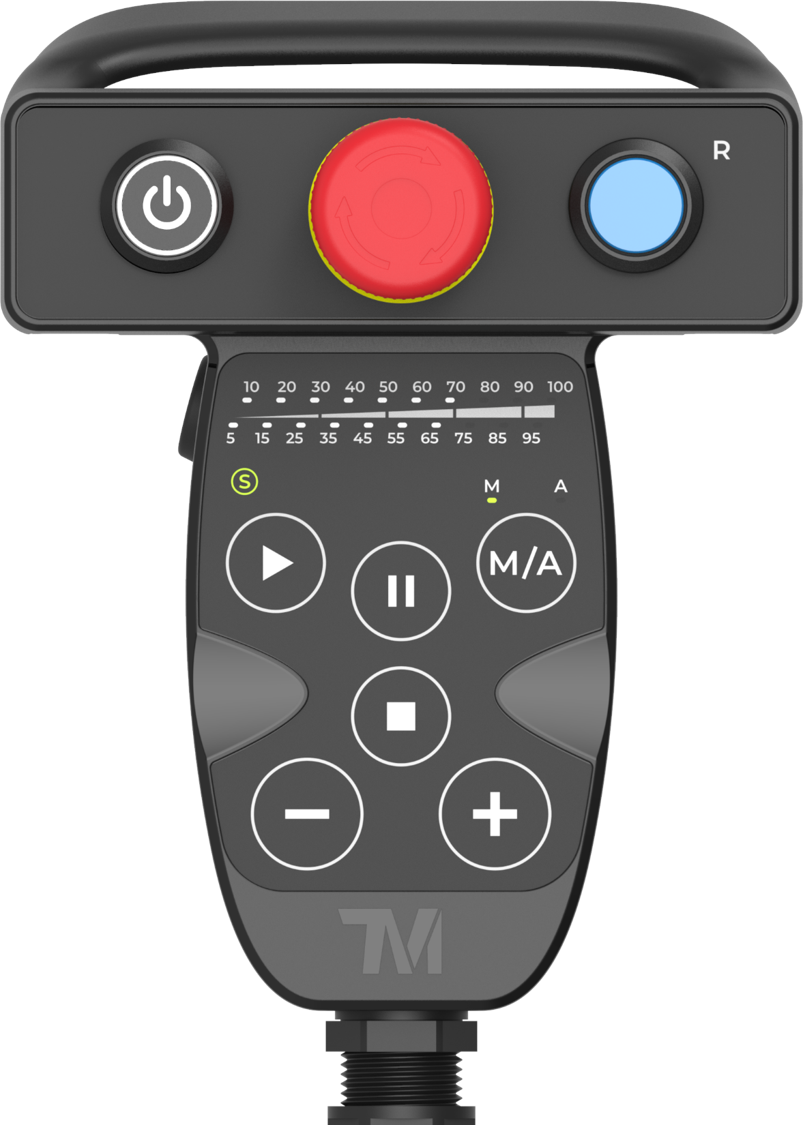
| SF19 | Robot Stick Enabling Switch | Protective Stop | Category 2 Stop | ||||||||||||||||||||||||||||||||||||
| SF20 | Reset Output | (Output function) | |||||||||||||||||||||||||||||||||||||
| SF21 | Robot Stick Reset | (Reset safety state) | |||||||||||||||||||||||||||||||||||||
| SF22 | Enabling Switch on End-module | Protective Stop | Category 2 Stop | ||||||||||||||||||||||||||||||||||||
| SF23 | User Connected External Bumping Sensor Input | Protective Stop | Category 2 Stop | ||||||||||||||||||||||||||||||||||||
| SF24 | End-Point Reduced Speed Limit | Protective Stop | Category 2 Stop | ||||||||||||||||||||||||||||||||||||
| SF25 | User Connected MODE Switch Input | (Change safety criteria) | |||||||||||||||||||||||||||||||||||||
| SF26 | User Connected Reset Input | (Reset safety state) | |||||||||||||||||||||||||||||||||||||
| SF27 | User Connected Soft Axis Settings Switch Input | (Change safety criteria) | |||||||||||||||||||||||||||||||||||||
| SF28 | Enabling Switch Output | (Output function) | |||||||||||||||||||||||||||||||||||||
| SF29 | MODE Switch Output | (Output function) | |||||||||||||||||||||||||||||||||||||
| SF30 | Safe Home Output | (Output function) | |||||||||||||||||||||||||||||||||||||
| Note:
1. Stop categories in accordance with IEC 60204-1. 2. The structure category according to ISO 13849-1:2015. 3. PL (Performance Level) in accordance with ISO 13849-1:2015.
Improvement & Scenario #
Although the ISO/DIS 10218-1:2020 is yet published, the TRSS5.0 is designed according to this version. In order to meet the requirements and the future market trend, TRSS5.0 has added certain safety designs:
ISO/DIS 10218-1:2020: The safety function shall provide a safety function output when the robot is in a monitored standstill condition.
SF2 Encoder Standstill Output comes with a safety output function to monitor the movement of each robot actuator through the joint encoder after triggered Category 2 Stop within a fixed time. If the joint encoder movement exceeds the acceptable range, the robot will perform a Category 0 Stop.
ISO/DIS 10218-1:2020: Each teach pendant that can initiate motion or cause movement(s) shall have an enabling device in accordance with 5.13.
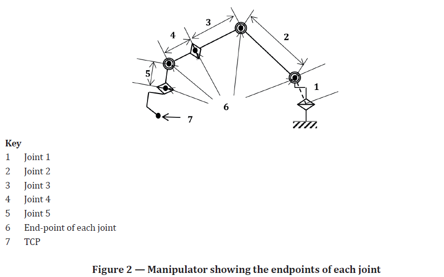
ISO/DIS 10218-1:2020: With the reduced-speed safety function, the speed of the TCP and the endpoint(s) of each joint of the manipulator shall not exceed 250 mm/s including the effects of any auxiliary axis. It should be possible to select speeds lower than 250 mm/s as the maximum limit. The robot shall have reduced-speed safety function to enable limiting the end-effector or workpiece speed(s) to 250 mm/s or less. This safety function shall be used with reduced-speed manual mode. Figure 2 shows the end-points of each joint of the manipulator. (Figure 2 from ISO/DIS 10218-1:2020)
The robot will totally under Local Control while user is controlling the robot using the Robot Stick, which ensures the robot will not allow motion by receiving peripheral commands. The safety can be totally ensured. The Local Control and Remote Control according to Robot Stick status and operation can be summarized as the table below:
|
|||||||||||||||||||||||||||||||||||||||