Why need this method #
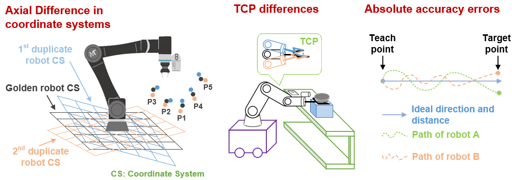
There exists robot differences because of axial differences between each robot coordinate system, TCP posture differences and absolute accuracy errors. So if you directly run the project imported from the golden robot, the duplicate robot will get a different result.
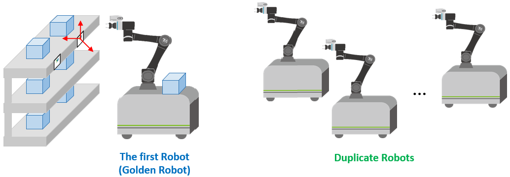
When you need to replace a new robot after the golden robot crashes, or have request of robot duplicate, such as AMR use, the traditional way is adjusting robots one by one.
Now just imagine, you have 100 robots and want them to do the same actions on 100 working stands, and if you spend T hours for adjusting the first robot, it still needs T*99 hours for adjusting other robots.
As you can see, this requires lots of time and manpower. To solve this problem, we provide this method to reduce adjusting time for duplicate.
Introduction #
To solve the axial difference problem, you can use a Landmark to build the vision bases on it, then edit points on this base.
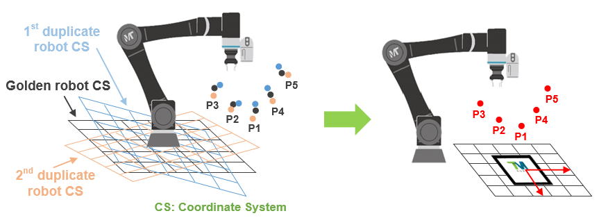
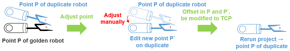
After that, choose a visual point of the golden robot as the calibration point, then re-adjust this point as a new point on the duplicate robot. Calculate the point offset and compensate to the duplicate robot’s TCP. Points applied this modified TCP will get the same compensation.
Limitations of use #
Point #
Modified TCP can only be used for points with the same posture of the calibration point.
Accuracy & Correction Range #
By measurement, it’s expected that the point error after calibration can be under 1 mm, but the points should follow the rule: points that are within 20 cm above the calibration point and ±10 cm in the X-Y directions with the calibration point at the center.
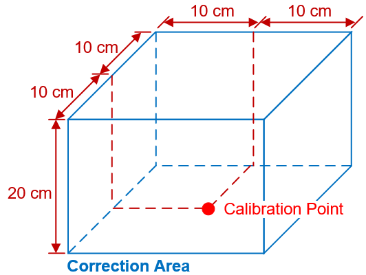
However, the error and range still depend on how you do calibration and the calibration accuracy at the calibration point. If the error is larger, the range would narrow down.
An Example of an AMR Application #
Here we edit a project of picking up a Front Opening Unified Pod (FOUP), and will use two robots to show how to do deviation calibration.
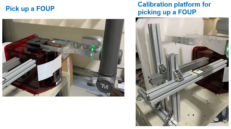
[The following can be omitted if no need]
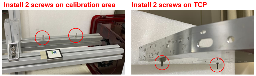
To let you directly observe the calibration result, we install two screws on the TCP, and setup an offline calibration platform. There also installs another two screws on the platform.
Requirements #
Two TM robots with the same model
A FOUP
A fork for picking up FOUPs
A landmark
[The following can be omitted if no need]
A platform can be setup on the working stand
A landmark
Two screws (on the platform)
Two screws (on the TCP)
Note:
- To reduce eye observational error, you can replace screws with calibration pins, and design locating holes for attachment.
- Use at least two pins for calibration (three is the best), one pin can only calibrate position without robot posture.
- If you need to setup another calibration stand, build it similarly to working scene as possible.
Golden Robot #
The first robot for editing the projects is the golden robot. We will edit the project with it in the working area, then move it to the calibration stand for calibration.
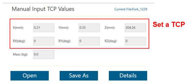
Set a TCP #
Before editing the project, navigate to Settings > TCP Settings to set a new TCP.
Edit project #
Steps:
- Edit two landmark alignment tasks first, the first one is for finding landmark by far look, the second is for positioning landmark by close look.
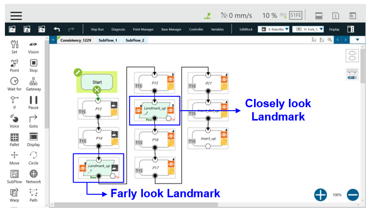
- During the second landmark task, suggest following some tips:
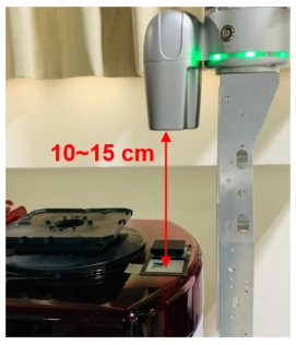
- Vision accuracy is also an influencing factor, so we suggest that the distance between the camera and the landmark is 10~15 cm.
- Before saving the landmark task, keep all scores at four corners of the landmark be larger than 0.8.
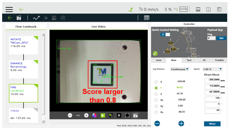
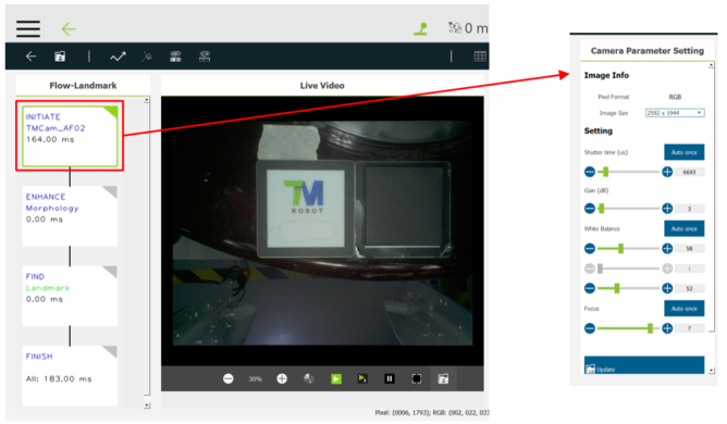
If the scores are too low or float greatly, you can re-adjust the robot observation angle or go back to flow page to re-adjust the camera parameters.
- Vision accuracy is also an influencing factor, so we suggest that the distance between the camera and the landmark is 10~15 cm.
- Edit some working points (remember to change the names of special points).
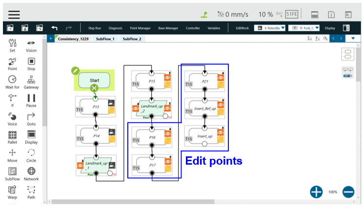
Adjust calibration platform [can be omitted] #
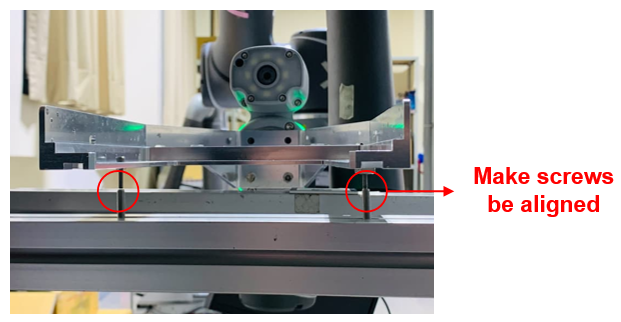
Install the screws on the TCP and move the robot to the calibration stand, then attach a landmark on the stand and redo the landmark positioning tasks. Choose a point from the project as the calibration point and then guide the robot to arrive at this point.
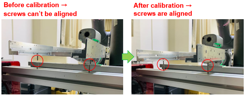
Here we choose the point of picking up the FOUP as the calibration point. Then adjust positions of screws on the calibration stand to let two sets of screws be aligned.
Backup or Duplicate Robots #
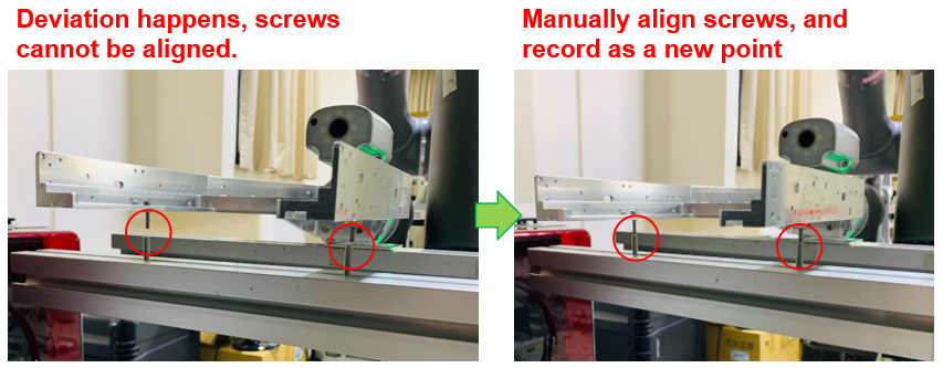
Import the project and TCP from the golden robot. First we directly run the project at the calibration stand, and find that the point deviation happens. Then we follow the steps below to do deviation calibration.
- Guide the robot to the calibration point, then manually adjust the point to the target position and record this position as a new point.
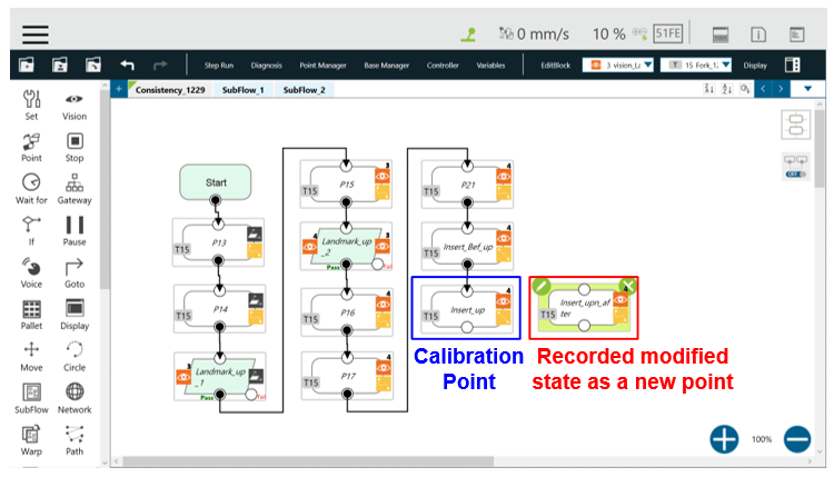
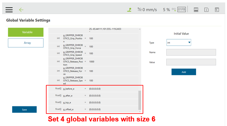
- Set 4 global variables as float array with size 6. Two are for recording the original and new point’s values (These variables can be set as local ones). One is for recording point offset. The last one is for recording modified TCP value.
- Create a new Subflow in the project, and do the following editing:
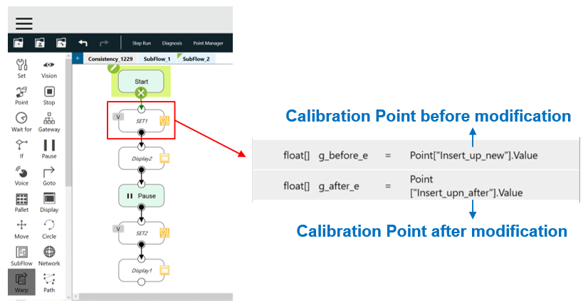
- Add a Set node (SET1), write the original and modified values of the calibration point to the first two variables.
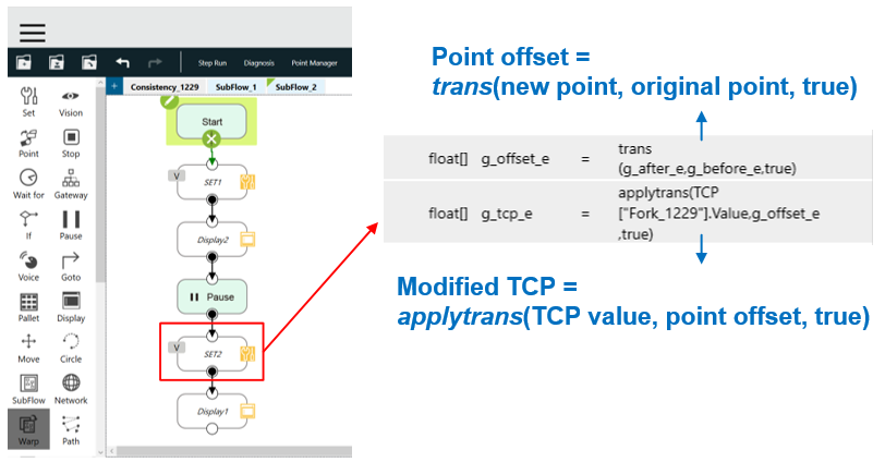
- Add a Set node (SET2), use function trans() to calculate the point offset. Then use function applytrans() to apply the offset to TCP and will calculate the modified TCP. [Function syntax can refer to Expression Editor for more details]
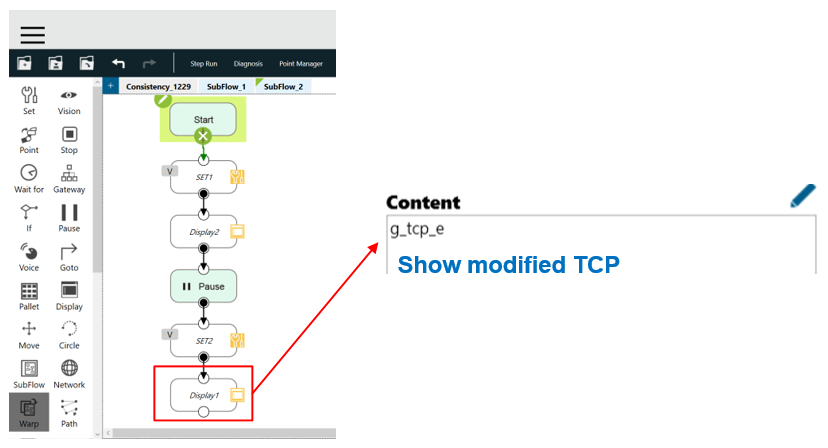
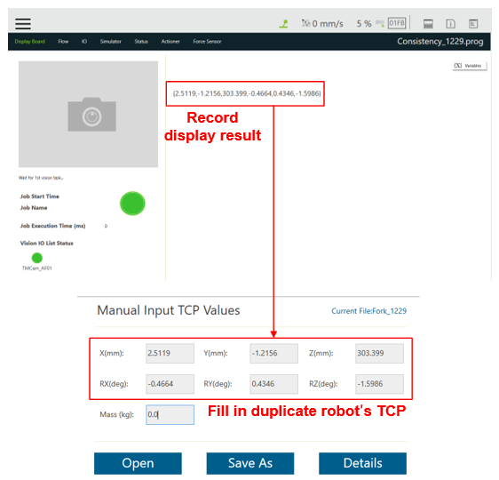
- Add a Display node, show the modified TCP calculated in SET2 node.
- Add a Set node (SET1), write the original and modified values of the calibration point to the first two variables.
- Run the Subflow and record the value on the View page, then fill in TCP parameters with this value.
- Run the main project again for validation:
[Can be omitted if no need]
We first validate the result at calibration stand, and find that the screws are almost aligned after calibration.
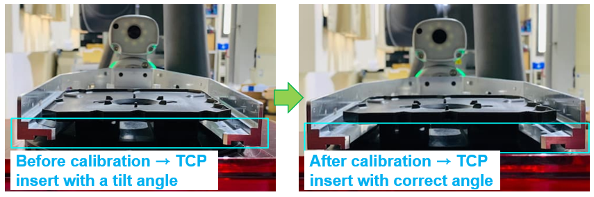
Then we move the robot to the working area to pick up a FOUP. As you can see, if we use the original TCP to run, the robot catches it with a tilt angle. But change to modified TCP, it gets a FOUP with correct posture.
Q&A #
Q1. Why the result is not satisfactory after the deviation calibration?
A1. The reasons are probably as follows:
- Landmark stability is bad → Open landmark task to adjust the camera parameters or the observation angle of the robot. Keep the landmark scores above 0.8.
- The calibration postures of two robots are dramatically different → Adjust the duplicate robot to let the posture almost be the same as golden’s, and redo calibration again.
- The postures of the points to be corrected are different from the calibration point’s → Modified TCP is only applicable to points with the same posture as the calibration point, if the point’s postures are different, you need to choose another point for calibration.
- Human eye error → Even though you use calibration pins to do calibration, it still exists about 0.3 mm in error. If you want to increase the calibration accuracy, you can design plugin fixture for calibration.
Q2. Can I use this modified TCP for all project points?
A2. No. See A1(3). Besides, even though the postures are the same, it’s still limited to correction range. Remember that the farther the distance between working and calibration points is, the larger the error is.
Q3. If the points spread too widely and would exceed the correction range, how to solve it?
A3. You need to divide the points into several groups, and choose a point from each group for calibration (notice the point posture). Then save the modified TCP as a new TCP, and use Tool Shift to change TCP of each group as the correspondingly new one.
Demo Video #
Video Link: Deviation Calibration


